
Tools Required
-
Digital Multimeter (DMM)
-
Back probes or T-pins
-
Connector Terminal/De-pinning tools
-
Fused Jumper Wires
-
Cummins INSITE (or equivalent diagnostic tool)
Vehicle Preparation
-
Safety: Park on a level surface, set the parking brake, and chock the wheels.
-
PPE: Wear safety glasses and gloves.
-
Power: Disconnect batteries via the master disconnect or negative cable before performing continuity tests.
-
Schematic Reference (2024+ Units):
-
X12N: 080A-0771
-
L9N: 080A-0764
-
Dual Drive Units: 080A-0609
-
Procedure
Part 1: Circuit Theory & Path
The APPS is a Hall effect sensor containing two redundant circuits (APS1 and APS2). Both receive a 5V supply from the ECM. Crucially, the APS1 signal voltage is designed to be double the APS2 signal voltage.
Sequential Connector Path:
-
6-Pin Connector (at pedal)
-
APPS Extension Harness (dual 3-pin connectors)
-
102-Pin Floor Pass-through
-
35-Pin ECM-to-Chassis Connector (near transmission)
-
23-Pin OEM Connector (final chassis-to-engine interface)
Part 2: Circuit Pinout Matrix (APS2 Focus)
Fault Code 1241 specifically relates to APS2 Signal (Wire 010).
| Wire & Function | APPS Cavity | 102-Pin Floor | 35-Pin Chassis | 23-Pin OEM Connector |
| 008 (APS2 +5V) | D | 93 | 6 | K |
| 010 (APS2 Signal) | E | 94 | 12 | W |
| 009 (APS2 Return) | F | 76 | 5 | L |
Common Failure Points (Fault Code 1241)
-
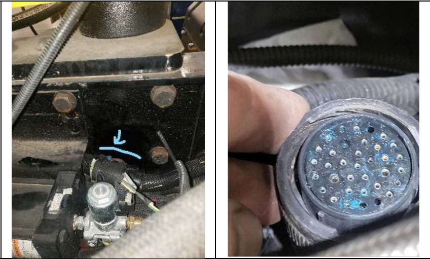
Corrosion at 35-Pin Connector: Located between the frame and left-side transmission; highly prone to water intrusion and green corrosion.
-
Spread Pins: Over-tightening or pulling the extension harness can spread the female terminals at the pedal connector, causing intermittent signal loss.
-
Harness Noise: APPS wires must be twisted. If the harness has been repaired and the wires are no longer twisted, electromagnetic noise can trigger signal integrity faults.
-
Direct Short: Inspect Wire 010 for chafing against the engine block or frame, causing a "short to ground" (FMI 4).
Validation & Repair Wrap-Up
-
Clear Codes: Use your diagnostic tool to clear all active and inactive codes.
-
Initial Test: Cycle the key, start the engine, and idle for one minute. Ensure the CHECK ENGINE lamp remains off.
-
Dynamic Test Drive: Test a full range of throttle inputs (acceleration, steady state, deceleration). Verify the engine has exited "Limp Home" mode and response is linear.
-
Final Scan: Perform a final scan post-test drive to ensure no codes have returned.